Inverter is a power control device that applies frequency conversion technology and microelectronic technology to control the AC motor by changing the frequency mode of the motor's working power.
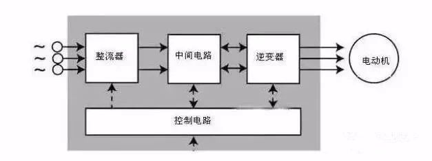
The inverter is mainly composed of rectification (AC to DC), filtering, inverter (DC to AC), braking unit, drive unit, and detection unit micro-processing unit.
The inverter relies on the opening and closing of the internal IGBT to adjust the voltage and frequency of the output power, and provides the required power voltage according to the actual needs of the motor, thereby achieving the purpose of energy saving and speed regulation.
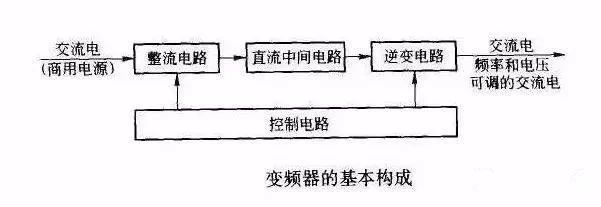
Inverter working principle
The frequency converter can be divided into two types of voltage type and current type.
The voltage type is an inverter that converts the DC of a voltage source into an AC, and the filtering of the DC circuit is a capacitor.
The current type is a frequency converter that converts the direct current of a current source into an alternating current. Its DC loop filter is an inductor. It is rectifier, rectifier, inverter.
The inverter's main circuit consists of a rectifier, a smoothing circuit and an inverter. It converts the power frequency power supply to a "rectifier" of DC power, and absorbs the "flat wave" of the voltage ripple generated by the converter and inverter. Circuit.
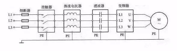
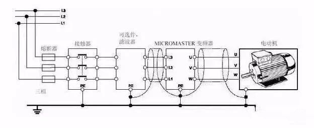
Inverter wiring diagram
The figure above is a wiring diagram of the inverter. In the installation of the inverter, there are some issues that need attention. For example, the inverter itself has strong electromagnetic interference, which will interfere with the work of some equipment, so we can add a cable sleeve to the output cable of the inverter. Or the control line in the inverter or control cabinet should be at least 100mm away from the power cable.
Inverter wiring method
Wiring of the main circuit
1. The power supply should be connected to the input terminals R, S, T of the inverter, and must not be connected to the inverter output (U, V, W), otherwise the inverter will be damaged.
After wiring, the broken wire ends must be cleaned. The broken wire ends may cause abnormalities, malfunctions and failures. The inverter must always be kept clean. When drilling holes in the console, be careful not to let debris, powder, etc. enter the inverter.
2. Between terminals + and PR, do not connect anything other than the recommended brake resistor option, or never short circuit.
3. Electromagnetic wave interference. The input / output (main circuit) of the inverter contains harmonic components, which may interfere with the communication equipment near the inverter. Therefore, install the optional radio noise filter FR-BIF or FRBSF01 or FR-BLF line noise filter to minimize interference.
4. For long-distance wiring, due to the influence of the parasitic capacitor charging current of the wiring, the fast response current limit function will be reduced, and the equipment connected to the secondary side will malfunction and cause a failure. Therefore, the maximum wiring length must be less than the specified value.
5. Do not install power capacitors, surge suppressors and radio noise filters on the output side of the inverter. Failure to do so will result in inverter failure or damage to the capacitor and surge suppressor.
6. In order to make the voltage drop within 2%, wire of appropriate type should be used for wiring. When the wiring distance between the inverter and the motor is long, especially in the case of low-frequency output, the torque of the motor will decrease due to the voltage drop of the main circuit cable.
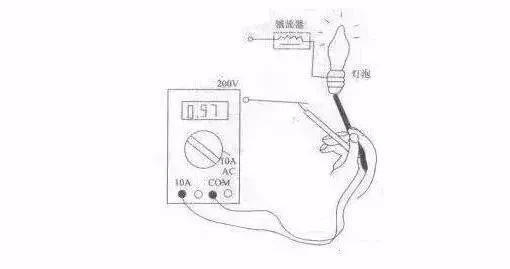
7. After operation, the operation of changing the wiring must be performed after the power is cut off for more than 10 minutes, and the voltage is checked with a multimeter. There is still dangerous high voltage on the capacitors for a period of time after power failure.
Control circuit wiring
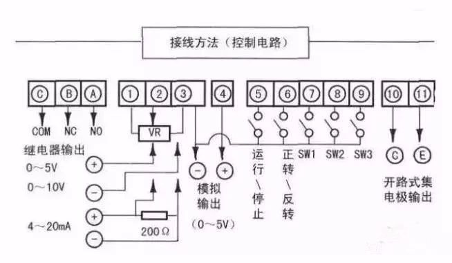
The control circuit of the inverter can be roughly divided into analog and digital.
1. The wiring of the control circuit terminals should be shielded or twisted pair, and it must be wired separately from the main circuit and strong current circuit (including 200V relay program circuit).
2. Because the frequency input signal of the control circuit is a small current, in the case of contact input, in order to prevent poor contact, the micro signal contact should use two parallel nodes or use twin contacts.
3. The control circuit wiring is generally selected from 0.3 to 0.75 square meters of cable.
Ground wire connection
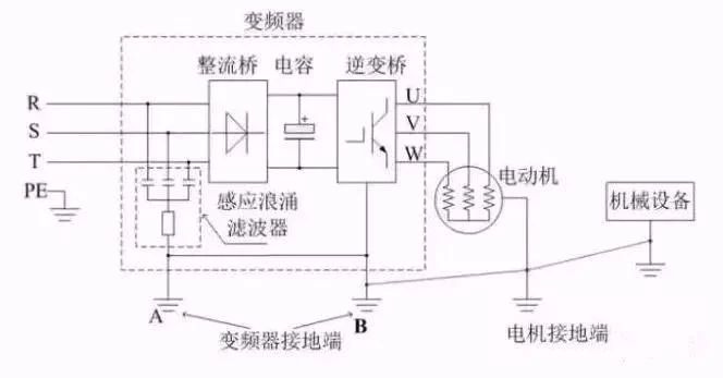
1. Due to the leakage current in the inverter, in order to prevent electric shock, the inverter and the motor must be grounded.
2. Special ground terminal for inverter grounding. To connect the ground wire, use crimp terminals with tin plating. When tightening the screws, be careful not to damage the buckle.
3. Lead is not included in tin plating.
4. Use a thick wire diameter for the grounding cable as much as possible, which must be equal to or greater than the specified standard. The grounding point should be as close as possible to the inverter. The shorter the grounding wire, the better.
The role of the inverter
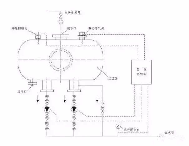
1. The inverter can adjust the power of the motor to achieve variable speed operation of the motor, thereby achieving the purpose of saving power. Examples are embodied in centrifugal fans and water pumps. When centrifugal fans and water pumps use frequency converters, operators can adjust the speed with frequency conversion, which can easily control the flow rate as needed, thereby saving energy.
2. The inverter can reduce the voltage fluctuation in the power line, and avoid the phenomenon of equipment tripping or abnormal operation if the voltage is abnormal.
3. The inverter can reduce the impact on the power grid, thereby effectively reducing the reactive power loss and increasing the effective power of the power grid.
4. The inverter can also reduce the wear between the transmission parts in the machine, which also reduces the cost to a certain extent and improves the stability of the system.
5. In addition, the inverter's control functions are very complete, which can be well coordinated with other control equipment or together to achieve centralized monitoring and real-time control, which solves many problems such as system compatibility problems for users.